Product Description
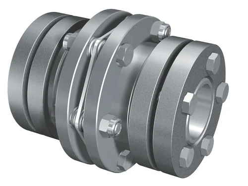
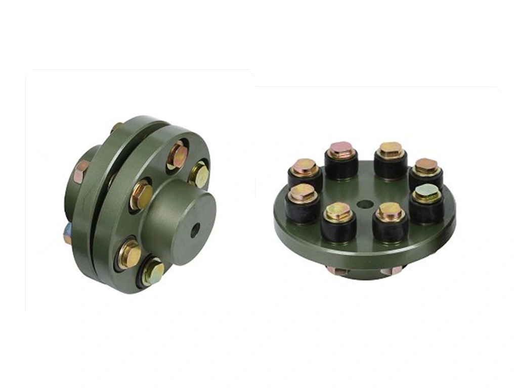
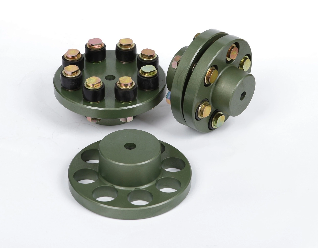
GFC-30X40 Type Jaw Flexible Coupling Jaw Coupling
GFC-30X40 Type Jaw Flexible Coupling Jaw Coupling
| model parameter | common bore diameter d1,d2 | ΦD | L | LF | LP | F | M | tightening screw torque (N.M) |
| GFC-14X22 | 3,4,5,6,6.35 | 14 | 22 | 14.3 | 6.6 | 5.0 | M2.5 | 1.0 |
| GFC-20×25 | 3,4,5,6,6.35,7,8,9,9.525,10 | 20 | 25 | 16.7 | 8.6 | 5.9 | M3 | 1.5 |
| GFC-20X30 | 3,4,5,6,6.35,7,8,9,9.525,10 | 20 | 30 | 19.25 | 8.6 | 5.9 | M3 | 1.5 |
| GFC-25X30 | 4,5,6,6.35,7,8,9,9.525,10,11,12 | 25 | 30 | 20.82 | 11.6 | 8.5 | M4 | 2.5 |
| GFC-25X34 | 4,5,6,6.35,7,8,9,9.525,10,11,12 | 25 | 34 | 22.82 | 11.6 | 8.5 | M4 | 2.5 |
| GFC-30×35 | 5,6,6.35,7,8,9,10,11,12,12.7,14,15,16 | 30 | 35 | 23 | 11.5 | 10 | M4 | 2.5 |
| GFC-30X40 | 5,6,6.35,7,8,9,10,11,12,12.7,14,15,16 | 30 | 40 | 25 | 11.5 | 10 | M4 | 2.5 |
| GFC-40X50 | 6,8,9,10,11,12,12.7,14,15,16,17,18,19,20,22,24 | 40 | 50 | 32.1 | 14.5 | 14 | M5 | 7 |
| GFC-40X55 | 6,8,9,10,11,12,12.7,14,15,16,17,18,19,20,22,24 | 40 | 55 | 34.5 | 14.5 | 14 | M5 | 7 |
| GFC-40X66 | 6,8,910,11,12,12.7,14,15,16,17,18,19,20,22,24 | 40 | 66 | 40 | 14.5 | 14 | M5 | 7 |
| GFC-55X49 | 10,11,12,12.7,14,15,16,17,18,19,20,22,24,25,28,30,32 | 55 | 49 | 32 | 16.1 | 13.5 | M6 | 12 |
| GFC-55X78 | 8,10,12,12.7,14,15,16,17,18,19,20,22,24,25,28,30,32 | 55 | 78 | 46.4 | 16.1 | 19 | M6 | 12 |
| GFC-65X80 | 14,15,16,17,18,19,20,22,24,25,28,30,32,35,38,40 | 65 | 80 | 48.5 | 17.3 | 14 | M8 | 20 |
| GFC-65X90 | 14,15,16,17,18,19,20,22,24,25,28,30,32,35,38,40 | 65 | 90 | 53.5 | 17.3 | 22.5 | M8 | 20 |
| GFC-80X114 | 19,20,22,24,25,28,30,32,35,38,40,42,45 | 80 | 114 | 68 | 22.5 | 16 | M8 | 20 |
| GFC-95X126 | 19,20,22,24,25,28,30,32,35,38,40,42,45,50,55 | 95 | 126 | 74.5 | 24 | 18 | M10 | 30 |
| model parameter | Rated torque (N.M)* |
allowable eccentricity (mm)* |
allowable deflection angle (°)* |
allowable axial deviation (mm)* |
maximum speed rpm |
static torsional stiffness (N.M/rad) |
moment of inertia (Kg.M2) |
Material of shaft sleeve | Material of shrapnel | surface treatment | weight (g) |
| GFC-14X22 | 5.0 | 0.1 | 1 | ±02 | 10000 | 50 | 1.0×10⁻⁶ | High strength aluminum alloy | Polyurethane imported from Germany | Anodizing treatment | 10 |
| GFC-20X25 | 5.0 | 0.1 | 1 | ±02 | 10000 | 50 | 1.0×10⁻⁶ | 15 | |||
| GFC-20X30 | 5.0 | 0.1 | 1 | ^02 | 10000 | 53 | 1.1×10⁻⁶ | 19 | |||
| GFC-25X30 | 10 | 0.1 | 1 | 10000 | 90 | 5.2X10⁻⁶ | 33 | ||||
| GFC-25X34 | 10 | 0.1 | 1 | £)2 | 10000 | 90 | 5.2×10⁻⁶ | 42 | |||
| GFC-30X35 | 12.5 | 0.1 | 1 | ±02 | 10000 | 123 | 6.2×10⁻⁶ | 50 | |||
| GFC-30×40 | 12.5 | 0.1 | 1 | 102 | 10000 | 123 | 6.2×10⁻⁶ | 60 | |||
| GFC-40X50 | 17 | 0.1 | 1 | 8000 | 1100 | 3.8×10⁻⁵ | 115 | ||||
| GFC-40X55 | 17 | 0.1 | 1 | ±02 | 8000 | 1100 | 3.8×10⁻⁵ | 127 | |||
| GFC-40X66 | 17 | 0.1 | 1 | 7000 | 1140 | 3.9×10⁻⁵ | 154 | ||||
| GFC-55X49 | 45 | 0.1 | 1 | ±02 | 6500 | 2350 | 1.6×10⁻³ | 241 | |||
| GFC-55X78 | 45 | 0.1 | 1 | 102 | 6000 | 2500 | 1.6×10⁻³ | 341 | |||
| GFC-65X80 | 108 | 0.1 | 1 | ±02 | 5500 | 4500 | 3.8×10⁻³ | 433 | |||
| GFC-65X90 | 108 | 0.1 | 1 | ±02 | 5500 | 4800 | 3.8×10⁻³ | 583 | |||
| GFC-80X114 | 145 | 0.1 | 1 | £)2 | 4500 | 5000 | 1.8×10⁻³ | 1650 | |||
| GFC-95X126 | 250 | 0.1 | 1 | ±02 | 4000 | 5000 | 2.0×10⁻³ | 1000 |
/* January 22, 2571 19:08:37 */!function(){function s(e,r){var a,o={};try{e&&e.split(“,”).forEach(function(e,t){e&&(a=e.match(/(.*?):(.*)$/))&&1
How does a flexible coupling handle electrical insulation between shafts?
Flexible couplings are typically not designed to provide electrical insulation between shafts. In most cases, flexible couplings are used solely for the purpose of transmitting mechanical power from one shaft to another while accommodating misalignment and absorbing shocks and vibrations. They do not offer any electrical isolation or insulation properties.
When electrical insulation is required between two rotating shafts in a system, additional components or specialized couplings are used. For applications where electrical isolation is necessary, insulated couplings or special insulation components can be employed. These types of couplings feature insulating materials, coatings, or designs that prevent electrical current from flowing between the connected shafts.
Insulated couplings can be beneficial in certain applications, such as electric motor drives or systems involving sensitive electronics. They help prevent stray currents, ground loops, and electrical interference that could potentially damage equipment or affect the accuracy of electronic signals. However, it is important to note that not all flexible couplings provide this electrical insulation capability, and users should carefully select couplings that meet the specific electrical isolation requirements of their application.
Summary: Flexible couplings, as standard mechanical components, do not inherently provide electrical insulation between shafts. They are primarily used for mechanical power transmission and misalignment compensation. If electrical insulation is needed between rotating shafts, insulated couplings or specialized components with insulating properties should be chosen to meet the specific requirements of the application.
What are the maintenance intervals and practices for extending the life of a flexible coupling?
Proper maintenance of a flexible coupling is essential to ensure its longevity and reliable performance. The maintenance intervals and practices for flexible couplings may vary depending on the coupling type, application, and operating conditions. Here are some general maintenance guidelines to extend the life of a flexible coupling:
- Regular Inspection: Conduct visual inspections of the coupling regularly to check for signs of wear, damage, or misalignment. Look for cracks, tears, corrosion, or any other visible issues.
- Lubrication: Some flexible couplings may require periodic lubrication to reduce friction and wear. Refer to the manufacturer’s guidelines for the appropriate lubrication type and schedule.
- Alignment Checks: Ensure that the connected shafts remain properly aligned. Misalignment can lead to premature wear and failure of the coupling and other components.
- Torque Monitoring: Monitor the torque levels in the system and ensure they are within the coupling’s rated capacity. Excessive torque can overload the coupling and cause damage.
- Temperature and Environmental Considerations: Ensure that the operating temperatures and environmental conditions are within the coupling’s specified limits. Extreme temperatures, aggressive chemicals, or corrosive environments can impact the coupling’s performance.
- Inspection After Shock Loads: If the system experiences shock loads or unexpected impacts, inspect the coupling for any signs of damage immediately.
- Replace Damaged or Worn Couplings: If any damage or wear is detected during inspections, replace the flexible coupling promptly to avoid potential failures.
- Periodic Re-Tightening: For certain coupling designs, periodic re-tightening of fasteners may be necessary to maintain proper clamping force.
- Follow Manufacturer’s Guidelines: Always follow the maintenance instructions provided by the coupling manufacturer. They can provide specific recommendations based on the coupling model and application.
It is crucial to develop a maintenance plan specific to the application and coupling type. Regularly scheduled maintenance, adherence to recommended practices, and proactive inspection can help identify issues early and prevent costly breakdowns. Additionally, record-keeping of maintenance activities can provide valuable data on the coupling’s performance and aid in future maintenance decisions.
Can flexible couplings accommodate high torque and high-speed applications?
Yes, flexible couplings can accommodate both high torque and high-speed applications, but the suitability depends on the specific design and material of the flexible coupling. Different types of flexible couplings have varying torque and speed capacities, and it’s crucial to select the right type of coupling based on the application requirements.
High Torque Applications:
Some flexible couplings, such as gear couplings and disc couplings, are designed to handle high torque levels. Gear couplings consist of toothed hubs that mesh with each other, providing a robust and efficient torque transmission. They are commonly used in heavy-duty industrial applications, such as steel mills, mining equipment, and power generation plants, where high torque loads are prevalent.
Disc couplings are also suitable for high torque applications. They use a series of flexible metal discs that can handle significant torque while compensating for misalignment. Disc couplings are often used in high-speed machinery and critical applications where precise torque transmission is essential.
High-Speed Applications:
Flexible couplings can also be used in high-speed applications. For instance, certain disc couplings, elastomeric couplings, and grid couplings are capable of handling high rotational speeds. These couplings have low inertia, which means they can respond quickly to changes in speed and provide efficient power transmission at high RPMs.
Elastomeric couplings, such as jaw couplings and tire couplings, are commonly used in various industrial applications, including pumps, compressors, and fans, where both torque and speed requirements are high. They offer good flexibility and damping properties, making them suitable for applications with high-speed variations and vibrations.
Considerations:
When selecting a flexible coupling for high torque and high-speed applications, several factors should be considered:
- The torque and speed ratings provided by the coupling manufacturer should be checked to ensure they meet or exceed the application’s requirements.
- The design and materials of the coupling should be suitable for the specific operating conditions, including temperature, environment, and potential exposure to corrosive substances.
- Proper alignment and installation of the coupling are critical to ensure optimal performance and prevent premature wear.
- In some cases, it may be necessary to use additional components, such as torque limiters or speed reducers, to protect the coupling and the connected equipment from excessive loads or speed fluctuations.
In conclusion, flexible couplings can indeed accommodate high torque and high-speed applications, but the appropriate coupling type and proper selection are essential to ensure reliable and efficient performance in these demanding conditions.


editor by CX 2024-03-13
by
Leave a Reply